Pipe Shoes
Guiding Set FS
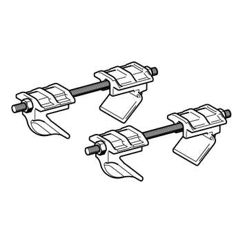


Application
Element for completing Guided Pipe Shoes based on Sliding Pipe Shoes.
Max. beam flange width t ≤ 30 mm
Scope of delivery
Pre-assembled Guiding Set containing:
4 Clamping hooks
2 Grub screws
Lift-off preventions:
2 for FS 240/260
4 for FS 280/300
Hexagon nuts:
4 for FS 80/120, FS 140/160 and FS 180/220 each
8 for FS 240/260 and 12 for FS 280/300
Technical Data
|
Flange Thickness [mm] | Beam Width 80 - 220 mm Tightening Torque [Nm] | Beam Width 221 - 300 mm Tightening Torque [Nm] |
|---|---|---|
| 5 - 10 | 40 | 15 |
| 11 - 20 | 25 | 15 |
| 21 - 30 | 20 | 15 |
| Material: | |
| Metal sheets: | Steel, HCP |
| Grub screws, nuts: | Steel, HCP |
| Clamping hooks: | Cast iron, HCP |
Approvals / Conformity

Pipe Shoe - external monitoring PDF | 626.1 KB