U Clamp RUC I


Application
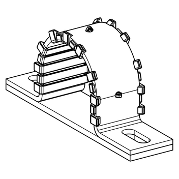
Guided Support for the installation of siFramo Beam Sections, Channels 41 and steel girders (H-, I- and Double-U) to support overlying pipelines. This U Clamp can be used as an alternative for Non-Grip (Guide) U Bolt applications. The sliding plate reduces friction between pipe and substructure. The plastic layer and the sliding plate ensure a galvanic isolation between pipe and U Clamp as well as substructure, so it's possible to fasten e.g. stainless steel pipes.
Scope of delivery
U Clamp RUC I with pre-assembled plastic layer. Sliding plate enclosed.
Installation
Depending on the existing substructure the following options are possible:
| a) | On top of siFramo Beam Sections with Self Forming Screws FLS |
| b) | On top of Channels 41 with bolts M10 and suitable Channel Nut |
| c) | On top of steel girders (H-, I- and Double-U) with bolts M10 |
Technical Data
| Type | perm. load Fy [kN] | perm. load Fz [kN] |
|---|---|---|
| 22 - 116 | 0.6 | 2.3 |
| 141 - 325,5 | 0.2 | 0.8 |
The perm. loads have been determined by load tests following DIN EN 13480-3 annex J.
For the installation on top of steel girders and Channels 41 the load capacities of these substructures (and connection parts) have to be verified.
| Material: | |
| Clamp body: | Steel, HCP |
| Layer and sliding plate: | Thermoplastic resins |
| Temperature range: | -20°C to +90°C (at layer and sliding plate) |
Also available with DUALSHIELD for high corrosion protection within C5H environments.